Microfluidic odorant delivery: zebrafish assay setup
A zebrafish olfactory assay fails when the stimulus is treated as a simple liquid exchange. It is not.
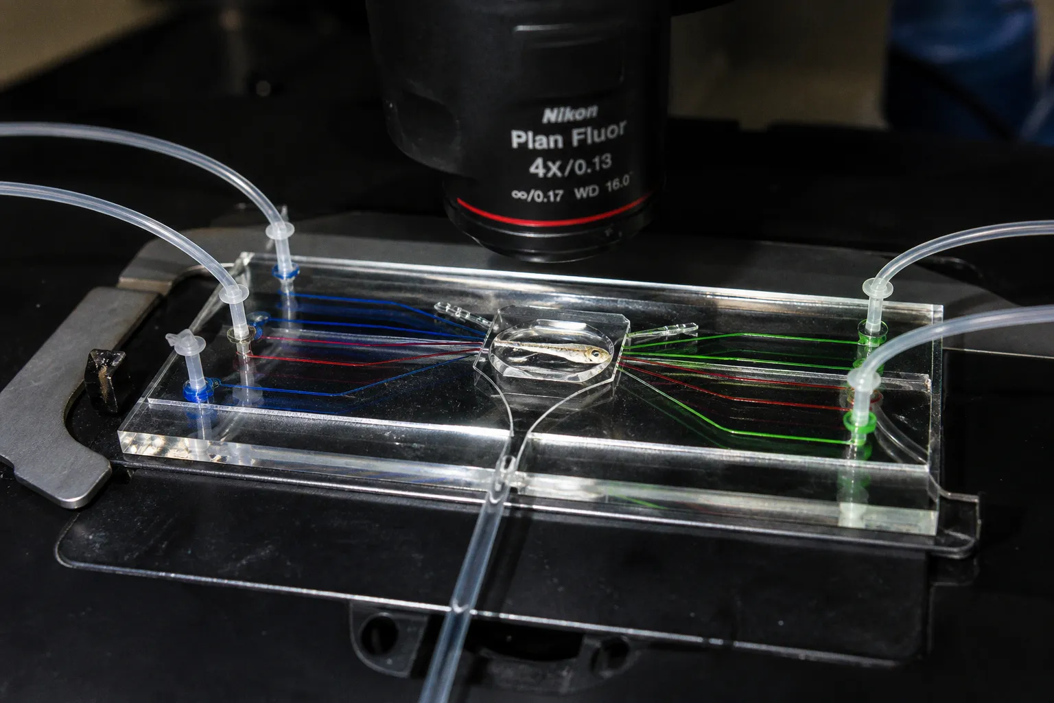
The experiment depends on three coupled variables: where the odorant enters, how fast its concentration changes, and what mechanical signal reaches the larva with the fluid.
That is the bottleneck in a microfluidic odorant delivery zebrafish protocol. Calcium imaging can resolve neuronal activity at high spatial and temporal resolution, but only if the odorant pulse is spatially defined and mechanically quiet. A switching event that changes pressure, flow direction, or meniscus position can activate behavior independently of sensory receptor signaling.
The solution is to engineer the fluid path first, then select the assay format. A restrained preparation, a partially free-swimming larva, and a non-anesthetized transport system answer different questions. They should not share the same chip geometry by default.
Start with the assay question, not the chip
Microfluidic platforms for larval zebrafish usually fall into three operational classes:
1. Acute stimulation with strong positional control.
The larva is restrained. The device directs a rapid chemical pulse across the face or into a selected nasal cavity. This format is suited to calcium imaging and short-latency neural responses.
2. Partial immobilization with preserved motor output.
The head is trapped while most of the body and tail remain free. The preparation allows measurement of tail, eye, and mouth movements during chemosensory stimulation.
3. Flow-based transport and behavioral positioning.
The larva remains non-anesthetized and is moved through a channel by combined visual and hydromechanical cues. This is useful when transport, orientation, or behavioral access matters more than maximal stimulus precision.
The first design decision is therefore not “which pump?” It is “which output must remain valid?”
If the endpoint is whole-brain calcium imaging, reduce movement and isolate the stimulus. If the endpoint is tail kinematics, preserve the tail. If the endpoint is naturalistic exploration, avoid a preparation that fixes the head and removes the animal’s ability to orient.
The chip does not improve an assay by itself. It improves the assay only when its geometry preserves the variable you intend to measure.
Match the preparation to the readout
| Assay objective | Larval state | Fluidic priority | Main risk |
|---|---|---|---|
| Whole-brain calcium imaging | Agarose-restrained or otherwise immobilized | Fast, repeatable stimulus exchange at the olfactory epithelium | Motion and pressure artifacts |
| Olfactory bulb mapping | Restrained, stable head position | Defined unilateral or bilateral delivery | Misassigned nasal input |
| Tail movement assay | Head trapped, body and tail free | Stable chemical zone with low shear | Mechanical restriction of motor output |
| Eye and mouth response | Partial immobilization | Face exposure with controlled flow | Flow-induced movement |
| Transport or orientation assay | Non-anesthetized | Coupled visual and hydromechanical guidance | Stress and unintended rheotaxis |
The zebrafish olfactory bulb contains approximately 140 glomeruli, with about 27 readily recognized in standard anatomical descriptions. That count is useful as a map, not as a promise that every glomerulus will be captured in one dorsal-view acquisition. Field of view, optical access, preparation stability, and indicator expression still set the practical limit.
Fish-on-Chips: separate nasal input without losing the animal
The Fish-on-Chips optofluidic platform addresses a specific problem: the two larval nasal cavities are separated by only about 100 µm. Conventional bulk delivery can expose both sides at once. That is acceptable for a bilateral odorant response. It is weak experimental control when the question concerns lateralized input, unilateral processing, or the relationship between nasal stimulation and whole-brain activity.
The platform uses laminar fluid flows to deliver odorant to either one nasal cavity or both. The flow regime is the control mechanism. Adjacent streams remain spatially organized instead of mixing immediately, allowing the operator to define chemical zones close to the larva.
This geometry gives the experiment two useful modes:
- Unilateral stimulation: deliver the odorant to one nasal cavity while maintaining a matched stream on the other side.
- Bilateral stimulation: combine or mirror the odorant streams so both cavities receive the intended stimulus.
The second stream should not be treated as empty space. It is part of the control condition. If one side receives odorant and the other receives buffer, the comparison includes both chemical asymmetry and any residual hydraulic asymmetry. Match the inlet arrangement, flow resistance, and switching sequence as closely as the device allows.
The behavioral arena
The Fish-on-Chips behavioral configuration uses a shallow two-dimensional swimming arena. Typical dimensions are:
- 60 mm × 30 mm × 1.5 mm for a swimming assay.
- 40 mm × 40 mm × 1.5 mm for a valence-oriented assay.
Slow, constant inflows enter at the corners. A central outlet removes fluid. The arrangement maintains relatively stable boundaries between chemical zones instead of allowing the odorant to disperse across the entire chamber.
That distinction matters for behavior. A larva does not respond only to odorant concentration. It responds to a concentration field that changes as the animal moves. If the field drifts, broadens, or reverses during the trial, the behavioral readout becomes difficult to interpret. The arena must therefore be treated as a spatial stimulus map.
Before adding larvae, verify the zones with a visible tracer or another non-biological indicator. The goal is not to produce a visually impressive boundary. The goal is to determine whether the boundary stays in place under the same inflow and outlet conditions used during acquisition.
Quantify three parameters:
1. Boundary position. Does the interface remain where the design predicts?
2. Boundary stability. Does it move when the pump starts, stops, or switches?
3. Washout behavior. How long does the arena retain signal after the odorant input is removed?
A behavioral assay needs a stable field over the full observation window. A neural assay needs a calibrated concentration transition at the nose. These are related requirements, but they are not identical.
Millisecond switching: define what “fast” means
A chemical valve can switch in milliseconds. That does not mean the larva receives a full-strength stimulus in milliseconds.
The Candelier et al. device provides a useful engineering reference. Its microfluidic channels are approximately 100 µm wide and 25–200 µm high. The channels are milled into PMMA slabs and sealed with 250 µm-thick PMMA sheets. The system achieves chemical switching in the 1–10 ms range under its defined operating conditions.
But the nominal concentration does not arrive immediately. The reported minimum stimulus duration to reach nominal concentration is approximately 35 ms. Reproducible pulses below 10 ms can be generated at sub-nominal concentrations.
That gives you two separate clocks:
- Switching time: how quickly the fluidic system changes streams.
- Exposure time: how long the stimulus must remain active to reach the target concentration at the relevant location.
Do not collapse these into one number in the protocol. A 5 ms valve event may produce a reproducible transient without producing a full-concentration odorant exposure. If the experimental question concerns threshold detection or temporal coding, that transient may be the intended stimulus. If the question concerns response amplitude at a defined concentration, it may not be sufficient.
A practical timing model
Build the sequence around measured fluidic behavior:
1. Establish the continuous buffer flow.
2. Confirm that the larva’s face sits in the intended flow region.
3. Trigger the odorant stream.
4. Record the valve or pump command time.
5. Record the arrival time at the observation point.
6. Record the neural or behavioral response from the same clock.
7. Return to buffer and measure washout before the next trial.
The command timestamp is not the sensory onset timestamp. Use a downstream optical or chemical indicator during calibration to estimate the delay between them. The exact concentration profile inside the nasal cavity remains difficult to infer directly, so report the calibrated delivery point and the fluidic timing rather than claiming a known intranasal concentration curve.
A short pulse also exposes mechanical weaknesses. Pressure transients can stimulate mechanosensory systems. They can move the larva, deform the epithelium, or change the local flow field. Microfluidic delivery reduces these artifacts only when the hydraulic transition is balanced.
Build the face flow around the larva
The Candelier design uses a continuous buffer flow of approximately 1–2 µL/s around the larva’s face. A V-shaped channel connects to an underpressurized waste container. This arrangement helps remove the resting fluid and limits cross-pollution between stimulus streams.
The continuous buffer flow is not a neutral detail. It establishes the baseline mechanical environment before every odorant pulse. Without it, a switch may replace a stagnant volume rather than exchange two controlled streams. The resulting response then combines chemical onset with bulk displacement.
Use the baseline period to test stability, not merely to wait. Look for:
- drift in larval position;
- changes in eye or mouth movement;
- tail deflection caused by the outlet;
- bubbles near the nose;
- visible backflow at the junction;
- delayed clearance after the stimulus ends.
The V-shaped waste path should remove fluid without creating a strong suction event at the face. The available facts do not establish a universal pressure limit for PMMA or PDMS bonds, so do not transfer a pump setting from one device to another as if it were a safe standard. Calibrate the actual assembly.
Cross-pollution is a timing problem
Cross-pollution can occur in several places:
- in the shared inlet line;
- at a valve manifold;
- at the channel junction;
- in the face-exposure region;
- in the waste path;
- during the return to buffer.
The most useful test is a sequence of alternating tracer pulses. Run the exact switching pattern planned for the assay. Quantify the residual signal after each pulse and the delay before the next stream reaches baseline. A channel that looks clean during a single exchange may fail under repeated stimulation.
Keep stimulus lines as short and symmetric as practical. Match their resistance where possible. Avoid unnecessary dead volume. A large upstream volume turns a sharp command into a broad exposure, even if the terminal channel is correctly dimensioned.
For a receptor-screening experiment, the consequence is direct. If L-arginine and L-lysine are delivered through a microfluidic olfactory stimulation system, residual amino acid from the previous pulse can produce an apparent response to the next condition. The resulting calcium trace may still look coherent. It will simply no longer identify a single ligand response.
Partial immobilization: preserve the movement you need
A 2017 device by Nady et al. uses a different compromise. It traps the larval head while leaving approximately 70% of the body and tail free in a downstream chamber. The system is designed for 5–7 dpf larvae and supports monitoring of tail, eye, and mouth movements.
This is a strong format for a zebrafish chemosensory transduction assay when the output includes motor behavior. It avoids the false choice between full restraint and unrestricted swimming. The nose remains positioned for controlled delivery. The tail remains available for quantification.
The compromise must be measured. Head trapping can alter:
- the range of head movement;
- the coupling between eye and body motion;
- the mechanical load on the trunk;
- the flow reaching the exposed body;
- the timing between sensory onset and tail response.
Do not describe the tail as “free” without defining the available space and the forces acting on it. A tail can move inside a chamber and still be constrained by wall contact, recirculation, or a persistent flow gradient.
Quantify the behavioral output
For tail responses, define the measurement before acquisition:
- tail-beat frequency;
- peak angular displacement;
- latency from calibrated stimulus arrival;
- left-right bias;
- response duration;
- recovery time after washout.
For eye and mouth movements, use the same logic. Separate onset latency from movement amplitude. A stimulus that produces a rapid eye response and a later tail response may engage different sensorimotor routes. Pooling both into one “behavioral score” removes that structure.
The chamber should also leave enough optical access to segment the tail and eyes consistently. A device that improves chemical delivery but forces a steep or obstructed imaging angle may reduce measurement quality elsewhere.
Non-anesthetized transport: use flow as a cue, not a disturbance
Microfluidic transport of non-anesthetized zebrafish larvae can combine visual and hydromechanical guidance. Moving gratings can engage the optomotor response. A flow rate of approximately 0.1 mL/min supplies the hydromechanical cue.
This format is operationally different from acute odorant delivery. The flow is no longer just a carrier. It becomes part of the behavioral environment. That creates a control requirement: distinguish movement caused by the visual cue, movement caused by the flow, and movement caused by the odorant.
Run the transport sequence without odorant first. Establish whether the larva reaches the intended position, how long transport takes, and whether the flow produces persistent orientation. Then add the chemical stimulus while holding the visual and hydromechanical parameters constant.
A useful control set includes:
1. visual cue without flow;
2. flow without visual cue;
3. matched flow with buffer;
4. matched flow with odorant;
5. odorant delivery without the transport sequence, if the preparation allows it.
The point is not to eliminate every environmental cue. That is rarely realistic in a living preparation. The point is to isolate which cue changes the measured output.
Avoid treating 0.1 mL/min as a universal transport setting. It is a reported operating value for a specific cueing approach, not a biological constant. Channel cross-section, larval age, inlet geometry, and pressure distribution determine the actual hydromechanical stimulus.
Connect delivery to sensory receptor signaling
A microfluidic chip controls the input. It does not identify the receptor pathway automatically.
For olfactory sensory neurons, calcium imaging with amino acids such as L-arginine or L-lysine can screen stimulus-responsive cells. The useful output is not simply a bright region in the olfactory epithelium. Map the response to the delivered condition, quantify onset and offset, and compare repeated pulses after washout.
A robust sensory receptor signaling experiment needs alignment across four layers:
- Fluidic layer: the stream arrives at the intended nasal region.
- Chemical layer: the stimulus identity and concentration remain controlled.
- Cellular layer: the imaged neurons respond above the defined baseline.
- Circuit layer: downstream activity is mapped without confusing delivery artifacts for sensory input.
The nasal cavities are close enough that a nominally unilateral stream may still generate bilateral exposure through diffusion, leakage, or geometry-dependent recirculation. The correct claim is therefore not “the contralateral side receives no stimulus.” The correct claim is that the platform is designed to deliver spatially separated streams and that the degree of separation must be calibrated for the specific device.
For olfactory bulb work, maintain a clear chain between input side and glomerular response. Use the same larval orientation, imaging plane, and stimulus sequence across trials. Do not infer complete bulb coverage from a partial optical field. Map the accessible structures and state the field limitations.
The cleanest calcium trace is still ambiguous if the chemical arrival time and the mechanical transition were never measured separately.
A compact setup sequence
A practical build can follow this order:
1. Define the endpoint.
Choose neural imaging, sensory neuron screening, motor output, or free-behavior positioning. This determines the acceptable level of restraint.
2. Select the flow architecture.
Use separated laminar streams for unilateral or bilateral nasal delivery. Use a stable arena for zone-based behavior. Use a partially immobilizing chamber when tail, eye, or mouth movement must remain measurable.
3. Calibrate the empty device.
Measure switching, arrival, washout, and boundary stability before introducing larvae. Record the command timestamp and the actual arrival signal separately.
4. Balance the hydraulic paths.
Match inlet resistance and reduce dead volume. Inspect the face region for bubbles, backflow, and pressure transients.
5. Verify the larval position.
Confirm that the nasal cavity, head, or body occupies the intended region. Position is part of the stimulus specification.
6. Run mechanical controls.
Deliver buffer switches with the same timing and flow changes as the odorant protocol. Quantify movement and neural activity during these controls.
7. Run chemical controls.
Alternate odorant and buffer streams. Measure carryover and define the minimum inter-trial interval from the observed washout, not from a convenient schedule.
8. Acquire with synchronized clocks.
Align fluidic command, calibrated arrival, imaging frames, and behavioral tracking. A response latency is meaningful only relative to the correct onset event.
9. Map the output.
For calcium imaging, quantify responding cells and time course. For behavior, quantify latency, amplitude, direction, and recovery. Keep these measures separate before any composite scoring.
Troubleshoot the failure at the layer where it begins
When the response is inconsistent, start with the fluidic record. Do not immediately blame receptor variability.
If the stimulus onset is slow
Inspect dead volume, channel height, inlet resistance, and the distance between the switching junction and the larva. A 1–10 ms valve transition can still produce a longer effective exposure if the downstream volume is large.
If buffer produces a response
Measure pressure and flow changes during the switch. Check for bubbles and larval displacement. A buffer control that changes the animal’s position is not a clean negative control.
If unilateral stimulation looks bilateral
Test the spatial boundary with a tracer. Inspect the face geometry and the relative flow resistance of the two nasal streams. The cavities are separated by only about 100 µm, so a small positioning error can alter the exposure pattern.
If repeated responses decay
Measure washout and carryover. The cause may be receptor adaptation, residual odorant, altered larval position, or a changing baseline flow. These mechanisms require different corrections.
If behavioral data are noisy
Separate chemical onset from mechanical onset. In a shallow arena, movement through a chemical boundary can change both odorant concentration and hydromechanical input. In a head-trap design, verify that the tail chamber does not introduce an unintended flow gradient.
If larvae fail to transport
Check the visual grating, flow direction, and flow rate independently. The reported hydromechanical transport condition is approximately 0.1 mL/min, but the effective cue depends on the device. A larva may receive a different local flow from the pump setting displayed on the controller.
For a broader treatment of how microfluidic geometry shapes sensory experiments, consult this overview of microfluidic sensory assay design.
The handover parameters
Before treating the assay as ready, lock these values in the methods record:
- larval age and preparation state;
- device material and channel dimensions;
- nasal cavity targeted, or bilateral exposure condition;
- baseline buffer flow;
- stimulus flow and switching command;
- measured arrival delay;
- measured time to nominal concentration, if available;
- washout time;
- arena or chamber dimensions;
- restraint geometry;
- mechanical-control response;
- chemical carryover between trials;
- imaging and behavioral timestamps.
The exact pressure limits of bonded PMMA or PDMS assemblies are not universal. Neither is the concentration profile inside the nasal cavity. Do not hide those unknowns behind a precise-looking pump value.
A reliable larval zebrafish odorant delivery setup is a calibrated input system. It isolates chemical timing from fluid mechanics, preserves the movement required by the endpoint, and maps the response to a defined anatomical route. Once those parameters are fixed, the chip becomes more than a delivery tool. It becomes part of the measurement architecture—and its errors become visible, testable, and correctable.